Kirchhoff’s rules – problems and solutions
1. What is the terminal voltage of the battery in the circuit below?
Solution
emf = electromotive force = the potential difference between the terminals when no current flow to an external circuit.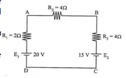
The terminal voltage (V) = the potential difference between the terminals when a current flows from the battery.
If no current is drawn from the battery, the terminal voltage equals the emf.
Known :
Resistor 1 (R1) = 2 Ω
Resistor 2 (R2) = 4 Ω
Resistor 3 (R3) = 4 Ω
emf 1 (E1) = 20 Volt
emf 2 (E2) = 15 Volt
Wanted : The terminal voltage (V)
Solution 1 :
The terminal voltage :
V = E1 – E2 = 20 – 15 = 5 Volt
Solution 2 :
Calculate the current flows in the circuit (I)
First, Choose the direction of each current. The direction can be chosen arbitrarily: if the current is actually in the opposite direction, it will come out with a minus sign in the solution.
Then, starting at any point in the circuit, we imagine traveling around a loop, adding emfs and IR terms as we come to them.
Second, When we travel through a source in the direction from – to +, the emf is considered to be positive; when we travel from + to -, the emf is considered to be negative.
Third, When we travel through a resistor in the same direction as the assumed current, the IR term is negative because the current goes in the direction of decreasing potential. When we travel through a resistor in the direction opposite to the assumed current, the IR term is positive because this represents a rise of potential.
The direction of current is chosen same as the clockwise direction :
E1 – I R1 – I R2 – I R3 – E2 = 0
20 – I (2) – I (4) – I (4) – 15 = 0
20 – 15 – I (2) – I (4) – I (4) = 0
5 – 10 I = 0
5 = 10 I
I = 5/10
I = 0.5 Ampere
The electric current flowing in the circuit is 0.5 Ampere. Electric current signed positive means the direction of electric current is the same as the clockwise direction.
Calculate the equivalent resistor (R) :
Resistor 1 (R1), resistor 2 (R2) and resistor 3 (R3) are connected in series. The equivalent resistor :
R = R1 + R2 + R3 = 2 Ω + 4 Ω + 4 Ω = 10 Ω
The terminal voltage in resistor R (V)
V = I R = (0.5)(10) = 5 Volt
2. In the circuit as shown in figure below, find the power dissipated in the 3-Ω resistor.
Solution :
Known :
Resistor 1 (R1) = 2 Ω 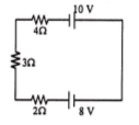
Resistor 2 (R2) = 3 Ω
Resistor 3 (R3) = 4 Ω
emf 1 (E1) = 8 Volt
emf 2 (E2) = 10 Volt
Wanted: The power dissipated in the 3-Ω resistor
Solution :
The power dissipated in the 3-Ω resistor :
P = V I
P = power, V = the voltage across the 3-Ω resistor, I = the current passes through the 3-Ω resistor
Calculate the electric current (I) passes through the 3-Ω resistor
The direction of current is chosen same as the clockwise direction :
E1 – I R1 – I R2 – I R3 + E2 = 0
8 – I (2) – I (3) – I (4) + 10 = 0
18 – 9 I = 0
18 = 9 I
I = 18 / 9
I = 2 Ampere
The electric current flowing in the circuit is 2 Ampere. Electric current signed positive means the direction of electric current is the same as the clockwise direction.
Circuits are connected in series so that the electric current flowing in the circuit = the electric current passes through the 3-Ω resistor = 2 Ampere.
Calculate voltage (V) across the 3-Ω resistor
V = I R2 = (2 A)(3 Ω) = 6 Volt
The power dissipated in the 3-Ω resistor :
P = V I = (6 Volt)(2 Ampere) = 12 Volt Ampere = 12 Watt
3. Based on the circuit as shown in the figure below, what is the potential difference between point A and B.
Known :
Resistor 1 (R1) = 2 Ω 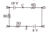
Resistor 2 (R2) = 3 Ω
Resistor 3 (R3) = 4 Ω
emf 1 (E1) = 8 Volt
emf 2 (E2) = 10 Volt
Wanted : The potential difference (V) between point A and B
Solution :
Calculate the electric current (I) flowing in the 3-Ω resistor
The direction of current is chosen same as the clockwise direction :
– E1 – I R1 – I R2 – E2 – I R3 = 0
– 8 – I (2) – I (3) – 10 – I (4) = 0
– 18 – 9 I = 0
– 18 = 9 I
I = -18 / 9
I = – 2 Ampere
The electric current flowing in the circuit is 2 Ampere. Electric current signed negative means the direction of electric current counterclockwise direction.
Circuits are connected in series so that the electric current flowing in the circuit = the electric current passes through the 3-Ω resistor = 2 Ampere.
Calculate the potential difference (V) across the 3-Ω resistor :
V = I R2 = (2 A)(3 Ω) = 6 Volt
4. Based on the circuit as shown in the figure below, what is the potential difference across the R3 resistor.
Known :
Resistor 1 (R1) = 2 Ω 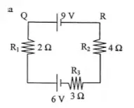
Resistor 2 (R2) = 4 Ω
Resistor 3 (R3) = 3 Ω
emf 1 (E1) = 6 Volt
emf 2 (E2) = 9 Volt
Wanted : The potential difference across the R3 resistor
Solution :
Calculate the electric current (I) passes through the R3 resistor
The direction of current is chosen same as the clockwise direction :
E1 – I R1 – E2 – I R2 – I R3 = 0
6 – 2I – 9 – 4I – 3I = 0
6 – 9 – 2I – 4I – 3I = 0
-3 – 9I = 0
-3 = 9I
I = -3/9
I = -1/3
The electric current flowing in the circuit is 1/3 Ampere. Electric current signed negative means the direction of electric current counterclockwise direction.
Circuits are connected in series so that the electric current flowing in the circuit = the electric current passes through the R3 resistor = 1/3 Ampere.
Calculate the potential difference (V) across the R3 resistor
V = I R3 = (1/3)(3) = 1 Volt
5. The potential electric between point C and D = 4 Volt, find R!
Known :
Resistor 1 (R1) = 2 Ω 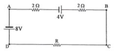
Resistor 2 (R2) = 2 Ω
Resistor 3 (R3) = R
emf 1 (E1) = 8 Volt
emf 2 (E2) = 4 Volt
The potential difference between C and D (VCD) = 4 Volt
Wanted : R
Solution :
VCD = I R
4 = I R
R = 4 / I
……………
Calculate the electric current (I) passes through the R resistor
The direction of current is chosen same as the clockwise direction :
– E1 – 2I + E2 – 2I – IR = 0
– 8 – 2I + 4 – 2I – I (4/I) = 0
– 8 – 2I + 4 – 2I – 4 = 0
– 8 + 4 – 4 – 2I – 2I = 0
– 8 – 4I = 0
– 8 = 4I
I = -8 / 4
I = -2 Ampere
The electric current flowing in the circuit is 2 Ampere. Electric current signed negative means the direction of electric current counterclockwise direction.
Circuits are connected in series so that the electric current flowing in the circuit = the electric current passes through the R resistor = 2 Ampere.
R :
R = 4 / I = 4 / 2 = 2 Ohm

