Electric circuits – problems and solutions
1. R1, = 6 Ω, R2 = R3 = 2 Ω, and voltage = 14 volt, determine the electric current in circuit as shown in figure below.
Known :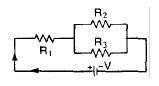
Resistor 1 (R1) = 6 Ω
Resistor 2 (R2) = 2 Ω
Resistor 3 (R3) = 2 Ω
Voltage (V) = 14 Volt
Wanted : Electric current (I)
Solution :
Equivalent resistor (R) :
R2 and R3 are connected in parallel. The equivalent resistor :
1/R23 = 1/R2 + 1/R3 = 1/2 + 1/2 = 2/2
R23 = 2/2 = 1 Ω
R1 and R23 are connected in series. The equivalent resistor :
R = R1 + R23 = 6 Ω + 1 Ω
R = 7 Ω
Electric current (I) :
I = V / R = 14 / 7 = 2 Ampere
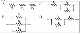
2. Which one of the electric circuits as shown below has the bigger current.
Solution :
The resistance of the resistor is R and the electric voltage is V.
Answer A.
R1, R2 and R3 are connected in series. The equivalent resistor :
RA = R1 + R2 + R3 = R + R + R = 3R
Electric current (I) :
![]()
Answer B.
R1, R2 and R3 are connected in parallel. The equivalent resistor :
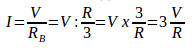
1/R = 1/R1 + 1/R2 + 1/R3 = 1/R + 1/R + 1/R = 3/R
RB = R/3
Electric current (I) :
Answer C.
R2 and R3 are connected in parallel. The equivalent resistor :
1/R23 = 1/R2 + 1/R3 = 1/R + 1/R = 2/R
R23 = R/2
R1 and R23 are connected in series. The equivalent resistor :
RC = R1 + R23 = R + R/2 = 2R/2 + R/2 = 3R/2
Electric current (I) :
![]()
Answer D.
R1 and R2 are connected in parallel. The equivalent resistor :
1/R12 = 1/R1 + 1/R2 = 1/R + 1/R = 2/R
R12 = R/2
R12 and R3 are connected in series. The equivalent resistor :
RD = R12 + R3 = R/2 + R = R/2 + 2R/2 = 3R/2
Electric current (I) :
![]()
3. R1 = 4 ohm, R2 = 6 ohm, R3 = 2 ohm, and V = 24 volt. What is the electric current in circuit as shown in figure below.
Known :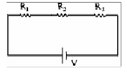
Resistor 1 (R1) = 4 Ohm
Resistor 2 (R2) = 6 Ohm
Resistor 3 (R3) = 2 Ohm
Voltage (V) = 24 Volt
Wanted : Electric current in circuit
Solution :
R1, R2 and R3 are connected in series. The equivalent resistor :
R = R1 + R2 + R3 = 4 + 6 + 2
R = 12 Ohm
Electric current :
I = V / R = 24 / 12 = 2 Ampere
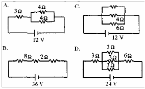
4. Which one of the electric circuits as shown below has the bigger current.
Solution
Electric current in circuit A.
The equivalent resistor :
R1 = 3 Ω, R2 = 4 Ω, R3 = 4 Ω, V = 12 Volt
R2 and R3 are connected in parallel. The equivalent resistor :
1/R23 = 1/R2 + 1/R3 = 1/4 + 1/4 = 2/4 = 1/2
R23 = 2/1 = 2 Ω
R1 and R23 are connected in series. The equivalent resistor :
R = R1 + R23 = 3 Ω + 2 Ω = 5 Ω
Electric current (I) :
I = V / R = 12 / 5 = 2.4 Ampere
Electric current in circuit B.
The equivalent resistor :
R1 = 8 Ω, R2 = 2 Ω, R3 = 2 Ω, V = 36 Volt
R1, R2 and R3 are connected in series. The equivalent resistor :
R = R1 + R2 + R3 = 8 + 2 + 2 = 12 Ω
Electric current (I) :
I = V / R = 36 / 12 = 3 Ampere
Electric current in circuit C.
The equivalent resistor :
R1 = 4 Ω, R2 = 4 Ω, R3 = 6 Ω, V = 12 Volt
R2 and R3 are connected in parallel. The equivalent resistor :
1/R23 = 1/R2 + 1/R3 = 1/4 + 1/4 + 1/6 = 3/12 + 3/12 + 2/12 = 8/12
R23 = 12/8 = 1.5 Ω
Electric current (I) :
I = V / R = 12 / 1.5 = 8 Ampere
Electric current in circuit D.
The equivalent resistor :
R1 = 3 Ω, R2 = 3 Ω, R3 = 3 Ω, R4 = 3 Ω, R5 = 6 Ω, V = 24 Volt
R2, R3 and R4 are connected in parallel. The equivalent resistor :
1/R234 = 1/R2 + 1/R3 + 1/R4 = 1/3 + 1/3 + 1/3 = 3/3
R234 = 3/3 = 1 Ω
R1, R234 and R5 are connected in series The equivalent resistor :
R = R1 + R234 + R5 = 3 + 1 + 6 = 9 Ω
Electric current (I) :
I = V / R = 24 / 9 = 2.6 Ampere
5. According to figure as shown below, determine :
A. Total resistance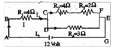
B. Electric current in circuit
C. Current I1
D. Current I2
Known :
Resistor 1 (R1) = 4 Ω
Resistor 2 (R2) = 4 Ω
Resistor 3 (R3) = 2 Ω
Resistor 4 (R4) = 3 Ω
Electric voltage (V) = 12 Volt
Solution :
A. Total resistance (R)
Resistor R2 and resistor R3 are connected in series. The equivalent resistor :
R23 = R2 + R3 = 4 Ω + 2 Ω = 6 Ω
Resistor R23 and resistor R4 are connected in parallel. The equivalent resistor :
1/R234 = 1/R23 + 1/R4 = 1/6 + 1/3 = 1/6 + 2/6 = 3/6
R234 = 6/3 = 2 Ω
Resistor R1 and resistor R234 are connected series. The equivalent resistor :
R = R1 + R234 = 4 Ω + 2 Ω = 6 Ω
The total resistance is 6 Ohm.
B. Electric current in circuit (I)
V = I R
V = electric voltage, I = electric current, R = electric resistance
Electric current :
I = V / R = 12 Volt / 6 Ohm = 2 Ampere
C. Electric current I1
Electric current in resistor R1 = electric current in circuit = 2 Ampere.
D. Current I2
Resistor R23 and resistor R4 are connected in parallel. The equivalent resistor R234 = 2 Ohm. 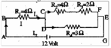
Electric current in resistor R234 = electric current in resistor R1 = 2 Ampere.
Voltage in resistor R234 is:
V = I R234 = (2 A)(2 Ohm) = 4 Volt
Voltage in resistor R234 = voltage in resistor R4 = voltage in resistor R23 = 4 Volt.
The equivalent resistor R23 is 6 Ohm.
Electric current in resistor R23 is :
I = V / R = 4 Volt / 6 Ohm = 2/3 Ampere
Electric current in resistor R23 = Electric current in resistor R2 = electric current in resistor R3 = 2/3 Ampere.
6. R1 = R2 = 10 Ω and R3 = R4 = 8 Ω. What is the electric current in circuit as shown in figure below ?
Known :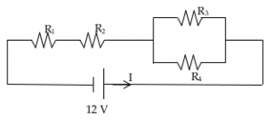
Resistor R1 = Resistor R2 = 10 Ω
Resistor R3 = Resistor R4 = 8 Ω
Electric voltage (V) = 12 Volt
Wanted : electric current (I)
Solution :
The equivalent resistor
Resistor R3 and resistor R4 are connected in parallel, the equivalent resistor :
1/R34 = 1/R3 + 1/R4 = 1/8 + 1/8 = 2/8
R34 = 8/2 = 4 Ω
Resistor R1, R2 and R34 are connected in series, the equivalent resistor :
R = R1 + R2 + R34 = 10 Ω + 10 Ω + 4 Ω = 24 Ω
Electric current :
I = V / R = 12 Volt / 24 Ohm = 0,5 Volt/Ohm = 0.5 Ampere
7. If the internal resistance of battery ignored, what is the electric current in the circuit shown in figure below.
Known :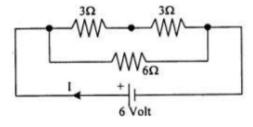
Resistor R1 = 3 Ohm
Resistor R2 = 3 Ohm
Resistor R3 = 6 Ohm
Electric voltage (V) = 6 Volt
Wanted : Electric current (I)
Solution :
Equivalent resistor
Resistor R1 and R2 are connected in series. The equivalent resistor :
R12 = R1 + R2 = 3 Ohm + 3 Ohm = 6 Ohm
Resistor R12 and resistor 3 are connected in parallel. The equivalent resistor :
1/R = 1/R12 + 1/R3 = 1/6 + 1/6 = 2/6
R = 6/2 = 3 Ohm
Electric current :
I = V / R = 6 / 3 = 2 Ampere
8. What is the total electric current in circuit as shown in figure below.
Known :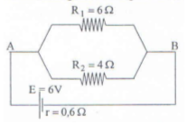
Resistor R1 = 6 Ohm
Resistor R2 = 4 Ohm
Electric current (V) = 6 Volt
Internal resistance (r) = 0.6 Ohm
Wanted : Electric current
Solution :
Resistor R1 and resistor R2 are connected in parallel. The equivalent resistor :
1/RP = 1/R1 + 1/R2 = 1/6 + 1/4 = 4/24 + 6/24 = 10/24
RP = 24/10 = 2.4 Ohm
Resistor RP and internal resistance (r) are connected in series. The equivalent resistor :
R = RP + r = 2.4 Ohm + 0.6 Ohm = 3.0 Ohm
Electric current in circuit :
I = V / R = 6 Volt / 3 Ohm = 2 Ampere
- What is an electric circuit?
- Answer: An electric circuit is a closed path or loop in which electric current can flow continuously. It typically consists of sources of voltage (like batteries), loads (like resistors, LEDs, motors), and conductors to connect them.
- What distinguishes a series circuit from a parallel circuit?
- Answer: In a series circuit, components are connected end-to-end, so there’s a single path for current. In a parallel circuit, components are connected across common points or junctions, providing multiple paths for current.
- How does Ohm’s Law relate voltage, current, and resistance in a circuit?
- Answer: Ohm’s Law states that the current () flowing through a conductor between two points is directly proportional to the voltage () across the two points and inversely proportional to the resistance (). It’s represented as .
- What is the role of a switch in an electric circuit?
- Answer: A switch controls the flow of current in a circuit. When closed, it allows current to flow; when open, it interrupts or stops the current flow.
- Why is a short circuit considered dangerous?
- Answer: In a short circuit, the resistance is very low, causing a very high current to flow. This can lead to overheating, fires, or damage to components and should be protected against with fuses or circuit breakers.
- What is the function of a fuse or a circuit breaker in a circuit?
- Answer: Both fuses and circuit breakers are protective devices designed to interrupt a circuit if the current exceeds a predetermined safe level. While fuses “blow” or “melt”, breaking the circuit, circuit breakers “trip”, and can be reset after they interrupt the circuit.
- How does Kirchhoff’s Current Law (KCL) describe currents at a junction in a circuit?
- Answer: Kirchhoff’s Current Law states that the sum of currents entering a junction is equal to the sum of currents leaving that junction. This is essentially a statement of the conservation of electric charge.
- What is the difference between AC (Alternating Current) and DC (Direct Current)?
- Answer: DC refers to the unidirectional flow of electric charge, typically from a battery or a DC power supply. AC, on the other hand, is an electric charge that changes direction periodically, like what’s supplied from the power grid in many countries.
- What does the term “ground” refer to in electrical circuits?
- Answer: “Ground” refers to a reference point in an electrical circuit from which other voltages are measured, or a common return path for electric current, or a direct physical connection to the Earth.
- Why are capacitors used in electric circuits?
- Answer: Capacitors store and release electrical energy. They’re used in circuits for various purposes, such as filtering, smoothing voltage fluctuations, coupling and decoupling AC signals, and timing elements in oscillators.

