Resistors circuits – problems and solutions
1. Which one of the resistors circuits, as shown in the figure below, has bigger resistance.
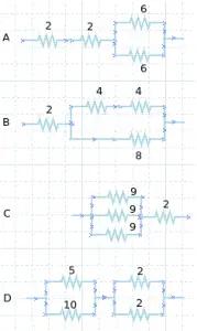
Answer A
R1 = 2 Ω, R2 = 2 Ω, R3 = 6 Ω, R4 = 6 Ω
R3 and R4 are connected in parallel. The equivalent resistor :
1/R34 = 1/R3 + 1/R4 = 1/6 + 1/6 = 2/6
R34 = 6/2 = 3 Ω
R1, R2 and R34 are connected in series. The equivalent resistor :
R = R1 + R2 + R34 = 2 Ω + 2 Ω + 3 Ω
R = 7 Ω
Answer B
R1 = 2 Ω, R2 = 4 Ω, R3 = 4 Ω, R4 = 8 Ω
R2 and R3 are connected in series. The equivalent resistor :
R23 = R2 + R3 = 4 Ω + 4 Ω = 8 Ω
R23 and R4 are connected in parallel. The equivalent resistor :
1/R234 = 1/R23 + 1/R4 = 1/8 + 1/8 = 2/8
R234 = 8/2 = 4 Ω
R1 and R234 are connected in series. The equivalent resistor :
R = R1 + R234 = 2 Ω + 4 Ω
R = 6 Ω
Answer C
R1 = 9 Ω, R2 = 9 Ω, R3 = 9 Ω, R4 = 2 Ω
R1, R2 and R3 are connected in parallel. The equivalent resistor :
1/R123 = 1/R1 + 1/R2 + 1/R3 = 1/9 + 1/9 + 1/9 = 3/9
R123 = 9/3 = 3 Ω
R123 and R4 are connected in series. The equivalent resistor :
R = R123 + R4 = 3 Ω + 2 Ω
R = 5 Ω
Answer D
R1 = 5 Ω, R2 = 10 Ω, R3 = 2 Ω, R4 = 2 Ω
R1 and R2 are connected in parallel. The equivalent resistor :
1/R12 = 1/R1 + 1/R2 = 1/5 + 1/10 = 2/10 + 1/10
1/R12 = 3/10
R12 = 10/3 Ω
R3 and R4 are connected in parallel. The equivalent resistor :
1/R34 = 1/R3 + 1/R4 = 1/2 + 1/2 = 2/2
R34 = 1 Ω
R12 and R34 are connected in series. The equivalent resistor :
R = R12 + R34 = 10/3 + 3/3 = 13/3
R = 4.3 Ω
2. What is the equivalent resistor in the circuit as shown in figure below.
Solution :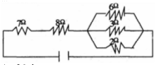
Resistor 6 Ω, 3 Ω and 2 Ω are connected in parallel. The equivalent resistor :
1/RP = 1/6 + 1/3 + 1/2 = 1/6 + 2/6 + 3/6 = 6/6
RP = 6/6 = 1 Ω
Resistor 7 Ω, 8 Ω and 1 Ω are connected in series. The equivalent resistor :
R = 7 + 8 + 1 = 16 Ω
3. What is the equivalent resistor in the circuit as shown in figure below.
Known :
Resistor 1 (R1) = 2 Ohm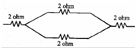
Resistor 2 (R2) = 2 Ohm
Resistor 3 (R3) = 2 Ohm
Resistor 4 (R4) = 2 Ohm
Wanted : The equivalent resistor
Solution :
Resistor R2 and resistor R3 are connected in parallel. The equivalent resistor
1/R23 = 1/R2 + 1/R3
1/R23 = 1/2 + 1/2 = 2/2
R23 = 1 Ohm
Resistor R1, resistor R23 and resistor R3 are connected in series. The equivalent resistor :
R = R1 + R2 + R3 = 2 + 1 + 2
R = 5 Ohm
- What is the primary function of a resistor in an electronic circuit?
- Answer: A resistor’s primary function is to limit or control the flow of electric current in a circuit. It introduces resistance to the flow of electrons, which can be useful for controlling circuit behavior or protecting components.
- How do series and parallel resistor configurations differ in terms of total resistance?
- Answer: In a series configuration, the total resistance is the sum of individual resistances: . In a parallel configuration, the inverse of the total resistance is the sum of the inverses of the individual resistances: 1/.
- Why might one choose to connect resistors in parallel rather than in series?
- Answer: Connecting resistors in parallel can decrease the total resistance of a circuit, potentially increasing the total current flow. It can also provide redundancy—if one resistor fails, the circuit can still operate with the other parallel resistors.
- How does the power rating of a resistor relate to its use in a circuit?
- Answer: The power rating indicates the maximum amount of power the resistor can dissipate as heat without being damaged. If a resistor in a circuit dissipates power beyond its rating, it can overheat and fail.
- Why do some circuits use variable resistors?
- Answer: Variable resistors, like potentiometers or rheostats, allow for adjustable resistance in a circuit. This can be useful for tuning or adjusting circuit parameters, such as the volume in audio devices or the brightness of a light.
- What happens if a resistor in a series circuit fails (opens)?
- Answer: If a resistor in a series circuit fails by becoming an open circuit, the entire circuit will open, and no current will flow through it. It’s akin to having a break in a water pipeline.
- What happens if a resistor in a parallel circuit fails (opens)?
- Answer: If a resistor in a parallel circuit fails by becoming an open circuit, the rest of the parallel branches will still carry current. The total resistance of the circuit will increase since one of the parallel paths has been removed.
- Why do some circuits utilize resistors with very high resistance values, sometimes in the order of megaohms?
- Answer: High resistance values can be used for various purposes, such as creating voltage dividers, biasing transistors, or working with very low current applications. They can ensure minimal current flow in certain parts of circuits, especially where sensitivity or precision is needed.
- How does temperature affect the resistance of most resistors?
- Answer: For many materials, resistance increases with temperature. The amount by which resistance changes with temperature is defined by the material’s temperature coefficient of resistance. Some resistors are specifically designed to have minimal change in resistance with temperature (these are called temperature-stable or low temp-co resistors).
- Why are pull-up and pull-down resistors used in digital circuits?
- Answer: Pull-up and pull-down resistors are used to define the default (idle) state of a digital input pin. A pull-up resistor connects an input pin to a positive voltage when no active signal is applied, ensuring a default HIGH state. Conversely, a pull-down resistor connects the input pin to ground, ensuring a default LOW state.

