fbpx

Resistivity

Article about Resistivity

Regarding electric current, the density of electric current has been discussed, so also the electric field has been explained in-topic about the electric field. The electric field and electric current are in a conductor if there is a potential difference in the conductor, whereas if there is no potential difference, then there is also no electric field and electric current.

In almost all metal conductors, the electric field is directly proportional to the density of the electric current, where the ratio of the electric field to the density of the electric current is constant. The value of the comparison of the electric field to current density is called resistivity. Mathematically, the relationship between the electric field, current density, and resistivity is stated in the equation:

Read more

Resistor color code

Article about the Resistor color code

The resistor is one component of an electrical circuit that functions to control the number of electric currents. In general, there are two types of resistors, namely wire coil resistors and carbon resistors. Wire roll resistors are usually used in the laboratory, made by wrapping fine wire on the surface of the insulator tube. Carbon resistors are typically used in electronic circuits, cylindrical, and have wires at both ends. The value of the carbon resistor resistance is expressed in color code and displayed on the surface of the resistor.

The resistance value of a resistor can be known by interpreting the resistor color code. To understand this, first look at the following table, then study the example problem to determine the resistor resistance value.

Read more

Resistors in series

Resistors in series 1

Article about the Resistors in series

If the resistors are connected as shown in the figure, the resistors are arranged in series. Resistor or electrical resistance in question can be in the form of resistor components, lights, or other electrical resistance.

The electric charge moves through resistance 1 (R1) = the electric charge moves through resistance 2 (R2) = the electric charge moves through resistance 3 (R3). Electric current (I) is an electric charge that flows during a certain time interval (I = Q / t), hence the electric current through resistance 1 (I1) = electric current through resistance 2 (I2) = electric current through resistance 3 (I3). Mathematically, the total electric current (I) = I1 = I2 = I3.

Read more

Electric resistance

Equation of the Electric resistance

In the topic of Ohm’s law, a formula that states the relationship between the voltage (V), electric current (I), and electrical resistance (R) has been derived. Mathematically expressed through equations:

Electric resistance 1

This equation shows that the electrical resistance (R) is directly proportional to the electric voltage (V) and inversely proportional to the electric current (I). If the mains voltage is greater than the electrical resistance is getting bigger, on the contrary, if the stronger the electric current gets bigger than the electrical resistance will be greater. This equation explains Ohm’s law only when the electrical resistance (R) is constant. If the electrical resistance is not constant, then this equation does not explain Ohm’s law, but explains the resistance of a conductor.

Read more

Resistors in parallel

Resistors in parallel 1

Article about the Resistors in parallel

If the resistors are connected as in the figure, the resistors are connected in parallel.

The electric current (electric current = electric charge that flows during a time interval) that enters the junction point is the same as the electric current exit from the junction point. There are several junctions so that the total electric current = the amount of electric current flowing in each junction. Mathematically, I = I1 + I2 + I3. While the electric potential difference or electrical voltage in each junction is the same.

I = V/R so the above equation changes to I = V/R1 + V/R2 + V/R3. The electric voltage is equal, so this equation changes to I = V (1/R1 + 1/R2 + 1/R3). If the equivalent resistance is 1/R then I = V (1/R). Thus, 1/R = 1/R1 + 1/R2 + 1/R3.

Read more

Source of electromotive force emf Internal resistance Terminal voltage

Article about Source of electromotive force emf Internal resistance Terminal voltage

Electric current flows in a closed circuit, from high potential to low potential. When an electric current moves through a component of electrical resistance, there is a reduction in electrical potential energy because electrical energy is used on this resistance. In order for the electric current to continue to flow from high potential to low potential,

there must be a device to add electrical potential energy, the tool is an electromotive force (emf) or more accurately called an electric voltage source. Emf or a voltage source is a component that converts a type of energy into electrical energy, such as batteries, solar cells, or electricity generators.

Read more

EMFs in series and parallel

EMFs in series and parallel 1

EMFs in series and parallel

If there are two or more sources of electromotive (emf) connected as shown in the figure, the emf is arranged in series.

The equivalent voltage source (ε) is:

ε = ε1 + ε2 + εn

The equivalent internal resistance (r) is:

r = r1 + r2 + rn

The electric current flowing through the external resistance (R) is:

Read more

Kirchhoffs first rule

Kirchhoff’s first rule 1
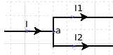
Kirchhoff’s first rule also called the rule of junction point states that the electric current that enters a junction point is the same as the electric current exit from that junction point. The junction point in an electrical circuit is the point where two or more of the two conductors meet, such as point a in the figure on the side.

I is the electric current that enters the junction point, while I1 and I2 are the electric currents that exit from the junction point, I = I1 + I2. Another example, observe the figure below.

Read more

Kirchhoffs second rule

Kirchhoff’s second rule states that the change in electric potential on the circumference of a closed circuit is zero. Kirchhoff’s second rule is based on the law of conservation of energy, which states that energy is eternal.

Kirchhoff’s second rule 1To better understand this, imagine the electric charge moving in a closed circuit, as in the figure. When an electric charge passes through an electrical resistance (R), the electrical potential energy is reduced because it is used on these resistances. If the electric charge passes through another electrical resistance, the electric potential energy decreases again because it is used again on the resistance. Furthermore, when the electric charge passes through the voltage source from a low potential to a high potential, the electric potential energy increases. When it returns to its original point, the electric potential energy is the same as before, where the change in electrical potential energy is zero. When applying Kirchhoff‘s second rule to an electrical circuit, we use the change in electrical voltage, not the change in electrical potential energy.

Read more

Electric power

Definition of electric power

The power learned in the work and Energy is defined as the work done during a certain time interval. Work is a process of energy change so that power can be understood as a change in energy that occurs during a certain time interval.

Electric power is a change in electrical energy during a certain time interval. In a review of electrical potential, it is explained that changes in electric potential energy occur when an electric charge passes through an electric potential difference.

Read more