Article about The Equation of capacitor circuit
A capacitor has a certain capacitance. If the required capacitance is not available, can be connected to two or more two capacitors to obtain the required capacitance. In order to properly connected the capacitor, it needs correct knowledge about the capacitor circuit. 🙂
 Before studying the capacitor circuit, first, understand the following symbols. Two vertical lines on the capacitor symbol represent two conductors on parallel plate capacitors. In the battery symbol, a longer vertical line represents a high potential (+) and a shorter vertical line represents a low potential (-). The horizontal line of both the capacitor symbol and the battery symbol represents the cable.
Series circuit
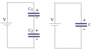 Two capacitors connected as in the left figure are called capacitors that are connected in series. The right figure is an equivalent capacitor that has a capacitance equivalent to the two series capacitors.
At first, the two capacitors were not electrically charged. After being connected to the battery, the plate of the capacitor C1 which is connected to the positive pole of the battery becomes positively charged. Because the electrons move out of it and the bottom plate of capacitor C2 which is connected to the negative pole of the battery becomes negatively charged because it receives electrons. Negatively charged electrons move because they are pulled by the positive pole of the battery, which is positively charged.
Then these electrons are rejected by the negatively charged of the negative pole of the battery, towards the bottom of the capacitor C2. The plate of the positively charged capacitor C1 pulls the electron from the top of the capacitor C2 so that the electrons move towards the bottom of the capacitor C1. As a result, the plate of the capacitor C1 becomes negatively charged and the plate of the capacitor C2 becomes positively charged.
The negative charge that exit from the top of the capacitor C1 is as much as the negative charge that enters the bottom of the capacitor C2. And the plate on the capacitor C1 gets a positive charge that is equal to the negative charge exit from it. Likewise, the negative charge on the bottom plate of the capacitor C1 is equal to the positive charge on the plate of the capacitor C2. So each conductor plate has the same amount of charge but the sign is different, where the top of the capacitor C1 is charged + Q.
The bottom of the capacitor C1 is charged -Q, the top of the capacitor C2 is charged +Q, and the bottom of the capacitor C2 is charged -Q. In a series circuit, the amount of electric charge on the capacitor C1 (Q1) = the amount of electric charge on capacitor C2 (Q2) = Q.
What about the electric potential? In a series circuit, the electric potential of the equivalent capacitor is equal to the electric potential of each capacitor, V = V1 + V2. The electric potential of capacitor C1 is V1 = Q/C1, the electric potential of capacitor C2 is V2 = Q/C2, and the electric potential of the capacitor is V = Q/C.
V = V1 + V2
Q/C = Q/C1 + Q/C2
Q/C = Q (1/C1 + 1/C2)
1/C = 1/C1 + 1/C2
If there are three capacitors that connected in series, the formula above changes to:
1/C = 1/C1 + 1/C2 + 1/C3
If there are four capacitors, 1/C4 is added. Likewise, if there are five capacitors and so on. This is the formula for determining the capacitance of the equivalent capacitor for capacitors connected in series.
Suppose C1 is 2 and C2 is 1 then the capacitance of the replacement capacitor is:
1/C = 1/C1 + 1/C2 = 1/2 + 1/1 = 1/2 + 2/2 = 3/2
C/1 = C = 2/3
Based on this calculation, it is concluded that the capacitance of the replacement capacitor is smaller than the capacitance of each capacitor connected in series.
Parallel circuit
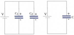 Two capacitors connected as in the left figure are called capacitors that are connected in parallel. The right figure is the replacement capacitor that has a capacitance equal to the two capacitors connected in parallel.
The plates of capacitors C1 and C2 are connected to the positive pole of the battery so that these two plates have high electric potential. Whereas the bottom plates of capacitors C1 and C2 are connected to the negative pole of the battery so that these two plates also have low electric potential. So it can be concluded that each capacitor that connected in parallel has a potential difference equal to the battery potential difference (V1 = V2 = V).
When the two capacitors that, connected in parallel, are connected to the battery, the positive pole of the battery pulls the electrons to the top plate. While the negative pole of the battery rejects the electrons into the lower plate so that the electron moves from the top to the bottom. The two plates lose electrons so that they become positively charged, and the two lower plates accept electrons so that they become negatively charged. The movement of electrons stops after the two conductor plates have a potential difference equal to the battery potential difference.
The top of the capacitor C1 and the bottom of the capacitor C1 store the same electric charge, but have an opposite sign. Likewise, the top piece of the capacitor C2 and the bottom piece of the capacitor C2 store the same electric charge but have opposite signs. If the electric charge stored in capacitor C1 is Q1 and the electric charge stored in capacitor C2 is Q2, then the amount of the electric charge stored in both capacitors that connected in parallel is Q = Q1 + Q2. So the total electric charge on the capacitor connected in parallel is equal to the amount of charge on each capacitor.
The electric charge in each capacitor connected in parallel is calculated by the equation Q1 = C1 ΔV and Q2 = C2 ΔV while the large electric charge on the replacement capacitor is calculated by the equation Q = C ΔV. Where Q is the electric charge, C is capacitance and ΔV is an electric potential difference. The equation Q = Q1 + Q2 is reformulated by substitute Q:
Q = Q1 + Q2
C ΔV = C1 ΔV + C2 ΔV
C ΔV = ΔV (C1 + C2)
C = C1 + C2
The potential difference of ΔV is equal, so eliminated from the equation.
If there are three capacitors connected in parallel, the formula above changes to:
C = C1 + C2 + C3
If there are four capacitors, C4 is added. Likewise, if there are five capacitors and so on. This is the formula for determining the capacitance of a replacement capacitor for capacitors connected in parallel.
If C1 is 2 and C2 is 1 then the capacitance of the replacement capacitor is:
C = C1 + C2 = 2 + 1 = 3
Based on this calculation, it is concluded that the capacitance of the replacement capacitor is greater than the capacitance of each capacitor connected in parallel.

