Article about Ray diagrams for diverging (concave) lens
If an object is on one side of the concave lens, the concave lens can form the image of the object. If the position of the object on one side of the concave lens is known, how to draw the image formation of the object? Suppose an object is on the left side of the concave lens, as shown in the figure below.
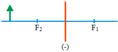 Orange line = the concave lens
Blue line = the principal axis
Arrow (green) = object
F1 = the focal length 1 and F2 = the focal length 2
The figure of the object’s image is obtained by drawing all the beams of light passing through the object, but this is less practical because there will be many lines representing light beams. For simplicity, just a few beams of light are chosen to represent all the beams of light passing through the object. Since this event involves refraction of light, the law of refraction of light must be obeyed when drawing the image formation.
Three beams of light or three rays
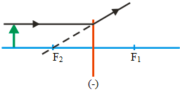 Ray 1 :
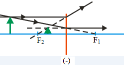
Ray 1 that comes to the concave lens is drawn parallel to the principal axis and touches the top edge of the object,
then refracted by the concave lens, where the beam of light refracts as if coming from the focal point. The incoming rays and the refractive rays that are must meet the law of refraction of light.
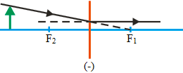 Ray 2 :
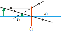
Ray 2 that comes towards the concave lens is drawn as if going to the focal point and touching the upper end of the object,
then refracted by the concave lens, where the refracted beam of light must parallel the principal axis. The incoming rays and the refractive rays that are draw must fulfill the law of refraction of light.
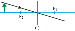 Ray 3 :
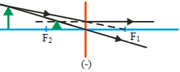
Ray 3 coming to the concave lens are drawn past the point of intersection of the concave lens and the principal axis.
Image formation (two rays)
The image formation can be drawn using only two rays, as shown below. If using two rays, there are three possible figures of the image formation.
Ray 1 and 2
Ray 1 and 3
Ray 2 and 3
Draw the images formation using only two rays need to be adjusted to the object distance from the concave lens. If the object distance from the concave lens is as in the figure above, there are three ways to draw the image formation using only two rays. If the object distance from the concave lens is different from the figure above,
for example, the object is between the focal point and the lens, then there is no need for three ways to draw the image formation, maybe there are only two ways to draw.
If you draw the image formation by the concave lens, you can choose one method and do not need to use two or three ways.
Image formation (three rays)
The image formation can be drawn using three rays, as shown in the figure below.
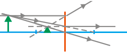
If the object distance from the concave lens is not as in the figure above, for example, the object is between the concave lens and the focal point,
or the object is between the focal point and the center of the curvature of the concave lens, then it is not necessarily the formation of image can be drawn using three ways like the figure above. There can only be two ways to draw the image formation.
Please observe the example image of the image formation by the concave lens, where the object distance from the concave lenses, varies, regarding the image formation by the concave lens.
10 conceptual questions and answers about ray diagrams for a diverging (concave) lens.
1. What is the purpose of a ray diagram in the context of a diverging lens?
A ray diagram is a schematic representation that shows how light rays change direction when they pass through a lens. In the context of a diverging lens, it illustrates how incident light rays diverge after passing through the lens and how they appear to originate from a single point on the same side of the lens as the incoming light (the focal point).
2. What are the standard rays used to draw a ray diagram for a diverging lens?
Three standard rays are used:
- The first ray travels parallel to the principal axis and then appears to originate from the focal point after refraction.
- The second ray passes straight through the center of the lens without being refracted.
- The third ray is directed towards the focal point on the opposite side of the lens and emerges parallel to the principal axis.
3. How does the image formed by a diverging lens differ in ray diagrams compared to a converging lens?
In ray diagrams, a diverging lens always forms a virtual, upright, and diminished image located on the same side of the lens as the object. On the other hand, a converging lens can form real, inverted images (if the object is beyond the focal point) or virtual, upright images (if the object is closer than the focal point).
4. Why is the image formed by a diverging lens always virtual as seen in ray diagrams?
In ray diagrams for diverging lenses, the refracted rays diverge and don’t actually meet on the other side of the lens. Instead, they appear to originate from a point on the same side of the lens as the object, which results in a virtual image.
5. How can the magnification of an image be determined from a ray diagram of a diverging lens?
The magnification of an image can be determined from a ray diagram by comparing the height of the image (taken from the principal axis to the top of the image) with the height of the object. In the case of a diverging lens, the image will always be smaller than the object, indicating a magnification less than 1.
6. What is the role of the principal axis in a ray diagram of a diverging lens?
The principal axis in a ray diagram is the line that passes through the center of the lens and is perpendicular to the lens. It serves as a reference line for tracing the path of light rays and locating the object, the image, and the focal points.
7. How is the focal point represented in a ray diagram of a diverging lens?
In a ray diagram, the focal point of a diverging lens is represented as the point from which light rays that are parallel to the principal axis appear to diverge after passing through the lens. This point is located on the same side of the lens as the incoming light.
8. In a ray diagram for a diverging lens, how is the distance between the lens and the image related to the object distance and the focal length?
The relationship is given by the lens formula 1/f = 1/v – 1/u, where f is the focal length, v is the image distance, and u is the object distance. Since a diverging lens has a negative focal length, the image distance is also negative, indicating that the image is formed on the same side of the lens as the object.
9. How can the location of the image be predicted using a ray diagram for a diverging lens?
The image location can be predicted by extending the refracted rays backwards on the object’s side until they meet. The point where the extensions of these rays intersect is the location of the image.
10. What happens to the image in the ray diagram as the object moves closer to a diverging lens?
As the object moves closer to the diverging lens, the image also moves closer to the lens but remains on the same side. Moreover, the image size becomes smaller as the object gets closer to the lens.

