Article about Ray diagrams for converging (convex) lens
If an object is on one side of the convex lens, the convex lens can form the image of the object. If the position of the object on one side of the convex lens is known, how to draw the image formation of the object? Suppose an object is on the left side of the convex lens, as shown below.
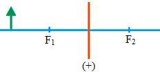 Orange line = convex lens
Blue line = principal axis
Arrow (green) = object
F1 = focal length 1 and F2 = focal length 2
The figure of the object’s image is obtained by drawing all the beams of light passing through the object, but this is less practical because there will be many lines representing light beams. For simplicity, just a few beams of light are chosen to represent all the beams of light passing through the object. Since this event involves refraction of light, the law of refraction of light must be obeyed when drawing the image formation.
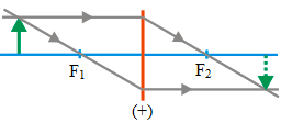
Three beams of light or three rays
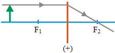 Ray 1 :
Ray 1 or the light beam 1 that comes towards the convex lens are drawn parallel to the principal axis of the lens and touch the upper end of the object,
then refracted by the convex lens, where the refracted beam of light must pass through the focal point 2. The incoming rays and refractive rays that are drawn must fulfill the law of refraction of light.
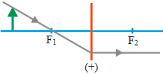 Ray 2 :
Ray 2 or the light beam 2 that come to the convex lens are drawn to pass the focal point 1 and touch the upper end of the object,
then refracted by the convex lens, where the refracted beam of light must parallel the principal axis. The incoming rays and the refractive rays that are drawn must fulfill the law of refraction of light.
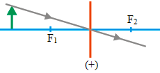 Ray 3 :
The ray 3 or the light beam 2 that come to the convex lens are drawn to pass through the point of intersection of the convex lens and the principal axis and touch the upper end of the object; then the light beam is forwarded.
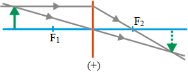
The formation of the image (two rays)
The image formation can be drawn using only two rays, as shown below. If using two rays, there are three possible images formation.
Ray 1 and 2
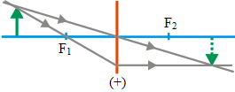
Ray 1 and 3
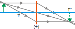
Ray 2 and 3
The figure the image formation using only two beams of light needs to be also adjusted by the object distance from the convex lens. If the object distance from the convex lens is as in the figure above, there are three ways to draw the image formation using only two rays. If the object distance from the convex lens is different from the figure above, for example, the object is between the focal point and the center of curvature,
then there is no need for three ways to draw the image formation, maybe there are only two ways to draw.
If you draw an image formation by the convex lens, you can choose one method.
The formation of the image (three rays)
The object formation can be drawn using three rays, as shown below.
If the object distance from the convex lens is not like the figure above, for example, the object is between the convex lens and the focal point, or an object is between the focal point and the center of the curvature of the convex lens, then it is no need to draw the image formation using three ways like the figure above. There can only be two ways to draw the image formation.
- Question: What are the three principal rays used in drawing ray diagrams for a converging lens? Answer: The three principal rays are: (1) the parallel ray that comes in parallel to the principal axis and goes through the far focal point after refraction; (2) the central ray that passes straight through the center of the lens without deviation; (3) the focal ray that approaches the lens passing through the near focal point and leaves the lens parallel to the principal axis.
- Question: How does the ray passing through the optical center of the lens behave in a ray diagram for a converging lens? Answer: The ray that passes through the optical center of the lens continues in the same direction without bending. This is because the two surfaces of the lens at the optical center are parallel and thus, there is no net deviation.
- Question: In a ray diagram for a converging lens, where does the ray that initially travels parallel to the principal axis refract to? Answer: The ray that initially travels parallel to the principal axis refracts through the lens and passes through the focal point on the other side of the lens.
- Question: How does the ray passing through the near focal point behave in a ray diagram for a converging lens? Answer: The ray passing through the near focal point, upon refraction, will exit the lens and travel parallel to the principal axis.
- Question: In a ray diagram for a converging lens, where do the refracted rays intersect when the object is beyond the focal point? Answer: When the object is beyond the focal point, the refracted rays intersect on the opposite side of the lens, forming a real and inverted image.
- Question: What does the intersection of the refracted rays represent in a ray diagram for a converging lens? Answer: The intersection of the refracted rays represents the location of the image formed by the lens. This can be a real or a virtual image, depending on the position of the object.
- Question: How does the image’s location change in a ray diagram as the object moves from infinity towards the lens? Answer: As the object moves from infinity towards the lens, the image moves from the focal point on the opposite side of the lens towards infinity. If the object crosses the focal point and comes within it, the image becomes virtual, upright, and magnified, and appears to be located on the same side as the object.
- Question: In a ray diagram for a converging lens, where do the refracted rays appear to diverge from when the object is within the focal point? Answer: When the object is within the focal point, the refracted rays appear to diverge from a point on the same side of the lens as the object, indicating the location of the virtual, upright, and magnified image.
- Question: What does it mean when the refracted rays in a ray diagram for a converging lens do not intersect? Answer: If the refracted rays do not intersect, it means that the image formed is virtual. This happens when the object is placed within the focal length of the lens. In this case, the rays appear to diverge from a point behind the lens on the object’s side.
-
Question: How does the material of the lens influence the ray diagram of a converging lens? Answer: The material of the lens affects its refractive index. A higher refractive index causes rays to bend more upon entering the lens, changing the positions of the focal points and thereby affecting the resulting ray diagram. However, the basic rules for drawing the ray diagram remain the same.

